General shear stress
The formula to calculate average shear stress is:

where
τ = the shear stress
F = the force applied
A = the cross sectional area
Other forms of shear stress
Beam shear
Beam shear is defined as the internal shear stress of a beam caused by the shear force applied to the beam.

where
V = total shear force at the location in question
Q = statical moment of area
t = thickness in the material perpendicular to the shear
I = Moment of Inertia of the entire cross sectional area
This formula is also known as the Jourawski formula.
Semi-monocoque shear
Shear stresses within a semi-monocoque structure may be calculated by idealizing the cross-section of the structure into a set of stringers (carrying only axial loads) and webs (carrying only shear flows). Dividing the shear flow by the thickness of a given portion of the semi-monocoque structure yields the shear stress. Thus, the maximum shear stress will occur either in the web of maximum shear flow or minimum thickness.
Also constructions in soil can fail due to shear; e.g., the weight of an earth-filled dam or dike may cause the subsoil to collapse, like a small landslide.
Impact shear
The maximum shear stress created in a solid round bar subject to impact is given as the equation:
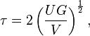
where
U = Change in Kinetic Energy
G = Shear Modulus
V = Volume of Rod
and
 ,
,

 ,
,
 = Mass Moment of Inertia
 = Angular Speed
Shear stress in fluids
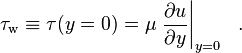
Any real fluid (liquids and gases included) moving along solid boundary will incur a shear stress on that boundary. The no-slip condition[2] dictates that the speed of the fluid at the boundary (relative to the boundary) is zero, but at some height from the boundary the flow speed must equal that of the fluid. The region between these two points is aptly named the boundary layer. For all Newtonian fluids the shear stress is proportional to the strain rate in the fluid where the viscosity is the constant of proportionality. However for Non Newtonian fluids, this is no longer the case as for these fluids the viscosity is not constant. The shear stress is imparted onto the boundary as a result of this loss of velocity. The shear stress, for a Newtonian fluid, at a surface element parallel to a flat plate, at the point y, is given by:

where
μ is the dynamic viscosity of the fluid,
u is the velocity of the fluid along the boundary, and
y is the height of the boundary.
Specifically, the wall shear stress is defined as:
In case of wind, the shear stress at the boundary is called wind stress.
Diverging fringe shear stress sensor
This relationship can be exploited to measure the wall shear stress. If a sensor could directly measure the gradient of the velocity profile at the wall, then multiplying by the dynamic viscosity would yield the shear stress. Such a sensor was demonstrated by A. A. Naqwi and W. C. Reynolds[3]. The interference pattern generated by sending a beam of light through two parallel slits forms a network of linearly diverging fringes that seem to originate from the plane of the two slits (see double-slit experiment). As a particle in a fluid passes through the fringes, a receiver detects the reflection of the fringe pattern. The signal can be processed, and knowing the fringe angle, the height and velocity of the particle can be extrapolated.
Micro-pillar shear-stress sensor
A further technique recently proposed is that of slender wall-mounted micro-pillars made of the flexible polymer PDMS, which bend in reaction to the applying drag forces in the vicinity of the wall. The deflection of the pillar tips from a reference position is detected optically and serves as a representative of the wall-shear stress. It allows the instantaneous detection of the streamwise and spanwise wall-shear stress distribution in turbulent flow up to high Reynolds numbers.
where
τ = the shear stress
F = the force applied
A = the cross sectional area
Other forms of shear stress
Beam shear
Beam shear is defined as the internal shear stress of a beam caused by the shear force applied to the beam.
where
V = total shear force at the location in question
Q = statical moment of area
t = thickness in the material perpendicular to the shear
I = Moment of Inertia of the entire cross sectional area
This formula is also known as the Jourawski formula.
Semi-monocoque shear
Shear stresses within a semi-monocoque structure may be calculated by idealizing the cross-section of the structure into a set of stringers (carrying only axial loads) and webs (carrying only shear flows). Dividing the shear flow by the thickness of a given portion of the semi-monocoque structure yields the shear stress. Thus, the maximum shear stress will occur either in the web of maximum shear flow or minimum thickness.
Also constructions in soil can fail due to shear; e.g., the weight of an earth-filled dam or dike may cause the subsoil to collapse, like a small landslide.
Impact shear
The maximum shear stress created in a solid round bar subject to impact is given as the equation:
where
U = Change in Kinetic Energy
G = Shear Modulus
V = Volume of Rod
and
,, = Mass Moment of Inertia = Angular SpeedShear stress in fluids
Any real fluid (liquids and gases included) moving along solid boundary will incur a shear stress on that boundary. The no-slip condition[2] dictates that the speed of the fluid at the boundary (relative to the boundary) is zero, but at some height from the boundary the flow speed must equal that of the fluid. The region between these two points is aptly named the boundary layer. For all Newtonian fluids the shear stress is proportional to the strain rate in the fluid where the viscosity is the constant of proportionality. However for Non Newtonian fluids, this is no longer the case as for these fluids the viscosity is not constant. The shear stress is imparted onto the boundary as a result of this loss of velocity. The shear stress, for a Newtonian fluid, at a surface element parallel to a flat plate, at the point y, is given by:
where
μ is the dynamic viscosity of the fluid,
u is the velocity of the fluid along the boundary, and
y is the height of the boundary.
Specifically, the wall shear stress is defined as:
In case of wind, the shear stress at the boundary is called wind stress.
Diverging fringe shear stress sensor
This relationship can be exploited to measure the wall shear stress. If a sensor could directly measure the gradient of the velocity profile at the wall, then multiplying by the dynamic viscosity would yield the shear stress. Such a sensor was demonstrated by A. A. Naqwi and W. C. Reynolds[3]. The interference pattern generated by sending a beam of light through two parallel slits forms a network of linearly diverging fringes that seem to originate from the plane of the two slits (see double-slit experiment). As a particle in a fluid passes through the fringes, a receiver detects the reflection of the fringe pattern. The signal can be processed, and knowing the fringe angle, the height and velocity of the particle can be extrapolated.
Micro-pillar shear-stress sensor
A further technique recently proposed is that of slender wall-mounted micro-pillars made of the flexible polymer PDMS, which bend in reaction to the applying drag forces in the vicinity of the wall. The deflection of the pillar tips from a reference position is detected optically and serves as a representative of the wall-shear stress. It allows the instantaneous detection of the streamwise and spanwise wall-shear stress distribution in turbulent flow up to high Reynolds numbers.


0 comments:
Post a Comment